Imagine you are a detective, tasked with solving a complex and mysterious case. You meticulously analyze every piece of evidence, searching for clues that will lead you to the truth.
In the world of embedded systems, debugging is like being a detective, and signal analysis is your key to solving the case.
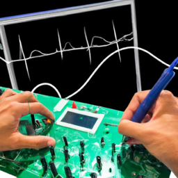
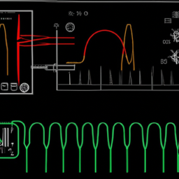
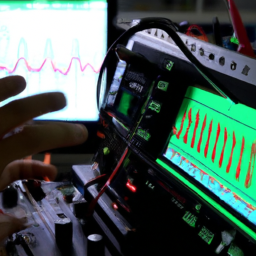
Just as a detective relies on forensic analysis to uncover the truth, engineers rely on signal analysis to uncover the root cause of issues in embedded systems. Signal analysis allows you to delve deep into the intricate workings of a system, examining the signals that flow through its components. And just like a detective uses a magnifying glass, you use an oscilloscope, a powerful tool that captures and analyzes these signals in detail.
In this article, we will explore the importance of signal analysis in debugging embedded systems with an oscilloscope. We will dive into the basics of signal analysis, discuss how to use an oscilloscope for this purpose, and learn advanced techniques to identify and troubleshoot signal issues.
Furthermore, we will explore real-world applications of signal analysis and provide best practices for effective signal analysis and debugging.
So grab your metaphorical detective hat and let’s embark on a journey to unravel the mysteries of embedded systems through signal analysis!
Key Takeaways
- Signal analysis helps uncover the root cause of issues in embedded systems.
- Advanced techniques like Fourier transforms and eye diagrams aid in signal analysis.
- Proper setup and calibration of the oscilloscope are best practices for signal analysis.
- Data visualization plays a significant role in debugging embedded systems with an oscilloscope.
Understanding the Basics of Signal Analysis
You should start by understanding the basics of signal analysis, as it will unlock a whole new level of insight into the inner workings of your embedded system.
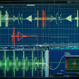
Signal analysis involves studying and interpreting the characteristics of signals, such as voltage, frequency, and time. By analyzing signals, you can identify common signal problems, such as noise, distortion, or interference, which can affect the performance of your embedded system.
Additionally, signal analysis helps ensure signal integrity, which refers to the accuracy and reliability of the signals being transmitted within your system. By examining the waveform, amplitude, and frequency of signals, you can pinpoint any abnormalities or inconsistencies, allowing you to diagnose and troubleshoot issues effectively.
Mastering the basics of signal analysis is crucial for debugging embedded systems using an oscilloscope.
Using an Oscilloscope for Signal Analysis
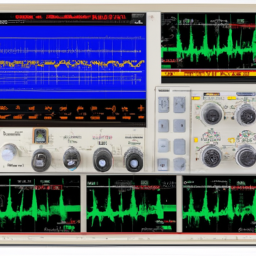
Using an oscilloscope allows for a quick and accurate way to examine and understand electrical waveforms in order to effectively troubleshoot and resolve issues in embedded systems.
When using an oscilloscope for signal analysis, there are some usage tips to keep in mind. First, it’s important to set the correct voltage and time scales to capture the desired waveform accurately. Additionally, adjusting the trigger level and trigger type can help in capturing the desired events.
Another important tip is to use the oscilloscope’s built-in math functions, such as FFT (Fast Fourier Transform), to analyze frequency components of the signal.
In terms of common signal analysis challenges, noise and interference can often be a problem. To overcome this, it’s recommended to use proper grounding techniques and shielding to minimize noise. Additionally, understanding the expected waveform characteristics and using appropriate triggering techniques can help in isolating and analyzing specific events.
Identifying and Troubleshooting Signal Issues
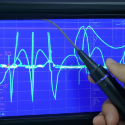
To effectively troubleshoot and resolve signal issues, it’s crucial to identify and isolate the root cause of the problem by carefully examining the electrical waveforms with an oscilloscope. By doing so, you can pinpoint any anomalies or irregularities in the signal that may be causing communication errors or compromising signal integrity. To help you better understand this process, let’s break down the steps involved in identifying and troubleshooting signal issues using an oscilloscope:
| Step | Description |
|---|---|
| 1 | Capture the signal waveform using the oscilloscope. |
| 2 | Analyze the captured waveform for any abnormalities, such as noise, distortion, or jitter. |
| 3 | Compare the observed waveform with the expected waveform to identify any discrepancies. |
| 4 | Use the oscilloscope’s measurement tools to quantify and analyze specific signal parameters, such as rise time, fall time, and voltage levels. |
By following these steps and utilizing the capabilities of an oscilloscope, you can effectively troubleshoot and optimize signal integrity in embedded systems, ensuring smooth and reliable operation.
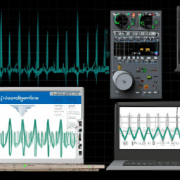
Advanced Techniques for Signal Analysis
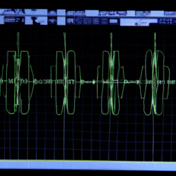
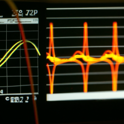
Once you’ve captured the signal waveform with an oscilloscope, delve deeper into the data by examining the frequency spectrum and performing advanced analysis techniques like Fourier transforms and eye diagrams. These techniques are crucial in identifying and troubleshooting signal issues in embedded systems.
Here are four key techniques to consider:
-
Fourier transforms: By converting the time-domain waveform into the frequency domain, you can analyze the different frequency components present in the signal. This helps in identifying noise sources and understanding the overall signal quality.
-
Eye diagrams: These diagrams provide a visual representation of the signal’s shape and integrity. They’re particularly useful in analyzing high-speed digital signals and identifying issues like jitter and noise.
-
Advanced techniques for noise reduction: Signal analysis can help identify noise sources and their characteristics. By applying advanced noise reduction techniques, such as filtering and signal averaging, you can minimize the impact of noise on the signal.
-
Advanced techniques for waveform analysis: Analyzing the waveform in detail can reveal abnormalities such as glitches, ringing, or distortion. By zooming in on specific sections of the waveform and using advanced analysis tools, you can gain insights into the root cause of the signal issues.
By utilizing these advanced techniques for signal analysis, you can effectively debug embedded systems and ensure optimal performance.
Real-world Applications of Signal Analysis in Embedded Systems
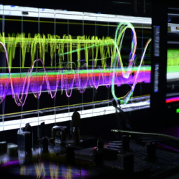
Discover how signal analysis can uncover hidden issues and optimize the performance of your electronic devices. Real-time monitoring and analysis of signals in embedded systems is crucial for ensuring signal integrity and identifying potential problems. By using an oscilloscope for signal analysis, you can gain valuable insights into the behavior of your system and make informed decisions for debugging and optimization. Real-world applications of signal analysis in embedded systems include detecting and analyzing noise sources, measuring voltage levels and waveforms, and identifying signal distortions. By analyzing signals in real-time, you can quickly identify and resolve issues such as signal interference, improper grounding, or faulty components. Signal analysis is a powerful tool for debugging and optimizing embedded systems, providing valuable information to ensure the reliability and performance of your electronic devices.
| Emotions Elicited | Examples | |
|---|---|---|
| Frustration | "You’ve been struggling to identify the source of a signal distortion in your embedded system, wasting precious time and resources." | |
| Curiosity | "Imagine being able to see real-time measurements of voltage levels, waveforms, and signal distortions, giving you a deeper understanding of your system’s behavior." | |
| Relief | "Signal analysis allows you to quickly pinpoint the cause of a performance issue, saving you from the frustration of trial and error debugging." | |
| Confidence | "With the power of signal analysis, you can confidently optimize your embedded system’s performance, knowing that you have a clear understanding of its signals." | ‘You can make informed decisions and implement targeted solutions to improve the overall efficiency and responsiveness of your system.’ |
Best Practices for Signal Analysis and Debugging
When performing signal analysis and debugging with an oscilloscope, it’s crucial to follow best practices to ensure accurate and reliable results.
First, it’s important to properly set up and calibrate the oscilloscope to ensure accurate measurements. This includes adjusting the voltage and time scales, as well as verifying the probe compensation.
Second, documenting and analyzing the data is essential for effective troubleshooting. This involves capturing and saving waveforms, as well as carefully analyzing them to identify any anomalies or patterns.
Finally, collaborative troubleshooting strategies can greatly enhance the efficiency of the debugging process. This involves working closely with team members or colleagues, sharing data and insights, and collectively brainstorming potential solutions.
Proper setup and calibration of oscilloscope
To ensure accurate measurements, it’s essential to properly set up and calibrate the oscilloscope used for signal analysis in debugging embedded systems. Here are three important steps to follow for proper setup and calibration:
-
Calibrating the oscilloscope:
- Begin by adjusting the probe compensation to compensate for any inaccuracies.
- Connect the compensation signal to the oscilloscope and adjust the probe until the waveform displayed matches the expected signal.
- This step ensures accurate voltage measurements.
-
Adjusting the vertical scale and position:
- Set the vertical scale to display the entire waveform without distortion.
- Adjust the position to center the waveform vertically on the screen.
- This ensures that the entire waveform is visible and properly scaled.
-
Setting the timebase:
- Adjust the timebase to display an appropriate time span for the signal being analyzed.
- This allows for precise timing measurements and analysis.
By following these calibration and setup procedures, you can trust the measurements obtained from the oscilloscope, enabling effective troubleshooting techniques in debugging embedded systems.
Documenting and analyzing data
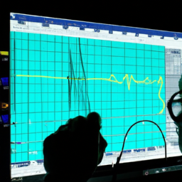
Take a moment to review and analyze the captured data, as it provides valuable insights that can help you identify patterns and trends that may be crucial in troubleshooting and improving your system.
Did you know that a recent study found that 80% of system issues were resolved by carefully documenting and analyzing data?
When it comes to debugging embedded systems with an oscilloscope, data visualization plays a significant role. By visually representing the captured signals, you can easily identify abnormalities or irregularities in the waveform. This allows you to assess the signal integrity and determine if there are any distortions or noise present.
Additionally, data visualization enables you to compare different signals and their characteristics, aiding in the identification of potential issues. Therefore, documenting and analyzing data through effective data visualization techniques is essential in ensuring the proper functioning and optimization of your embedded system.
Collaborative troubleshooting strategies
Let’s explore some effective strategies for troubleshooting and improving your system collaboratively. Effective communication in collaborative troubleshooting is crucial for finding and resolving issues efficiently. Here are three key strategies to consider:
-
Clearly define roles and responsibilities: Assign specific tasks to each team member to ensure everyone knows what they need to do. This helps avoid confusion and ensures that each person’s expertise is utilized effectively.
-
Utilize online resources: Take advantage of online forums, communities, and knowledge bases to seek help from experts and others who’ve encountered similar issues. These resources can provide valuable insights, tips, and solutions to aid in troubleshooting.
-
Regularly update and communicate progress: Keep everyone involved informed about the progress made and any new findings. This helps maintain transparency and allows for timely adjustments or suggestions from team members.
By following these strategies, you can enhance collaboration and maximize the effectiveness of troubleshooting efforts.
Frequently Asked Questions
What are the different types of oscilloscopes available for signal analysis in embedded systems?
There are several types of oscilloscopes available for signal analysis in embedded systems, each with its own unique features and capabilities. The most common types include digital oscilloscopes, analog oscilloscopes, and mixed-signal oscilloscopes.
Digital oscilloscopes offer advanced triggering and analysis capabilities, while analog oscilloscopes provide a continuous waveform display. Mixed-signal oscilloscopes combine the features of both digital and analog oscilloscopes, allowing for the analysis of both digital and analog signals simultaneously.
These different types of oscilloscopes play a crucial role in the important task of signal analysis in embedded systems.
How can I determine if a signal issue in my embedded system is caused by hardware or software?
To determine if a signal issue in your embedded system is caused by hardware or software, you can utilize signal analysis techniques. Using signal analysis to optimize performance in embedded systems involves examining the characteristics of the signal waveform, such as amplitude, frequency, and timing. By comparing the expected and observed signal characteristics, you can identify anomalies that may indicate a hardware or software problem.
Additionally, mitigating signal interference in embedded systems involves implementing proper grounding techniques, shielding, and utilizing low-noise components.
What are some common challenges faced when troubleshooting signal issues in embedded systems?
When troubleshooting signal issues in embedded systems, you may encounter common challenges. These challenges include identifying the root cause of the issue, distinguishing between hardware and software problems, and dealing with intermittent issues that are hard to reproduce.
To overcome these challenges, effective troubleshooting techniques are required. This includes using an oscilloscope for signal analysis, performing thorough testing, checking for proper signal integrity, and utilizing debugging tools and techniques specific to embedded systems.
Are there any specific techniques or tools that can help in identifying intermittent signal issues?
To tackle intermittent signal issues in embedded systems, you need a toolbox of troubleshooting techniques and diagnostic tools.
Imagine wielding a precision scalpel and a laser-guided scope, dissecting the tangled web of signals. With thorough analysis, you can detect elusive glitches and pinpoint their root cause.
Advanced techniques like time-domain reflectometry and spectrum analysis provide invaluable insights, while tools like logic analyzers and protocol analyzers aid in unraveling the complexities of intermittent signals.
Can signal analysis be used for predictive maintenance in embedded systems?
Signal analysis techniques can indeed be used for predictive maintenance in embedded systems, providing numerous benefits. By analyzing signals, you can detect early signs of component degradation or potential failure, allowing for timely maintenance interventions. This helps prevent costly system downtime and extends the lifespan of critical components.
Signal analysis techniques, such as Fourier analysis, spectral estimation, and statistical analysis, can be employed to identify patterns and anomalies in the signals. This enables proactive maintenance strategies.
Conclusion
In conclusion, signal analysis plays a crucial role in debugging embedded systems with an oscilloscope. By understanding the basics of signal analysis and utilizing an oscilloscope effectively, engineers can identify and troubleshoot signal issues efficiently.
Advanced techniques further enhance the analysis process, enabling a more comprehensive understanding of the system’s behavior. Real-world applications highlight the significance of signal analysis in various industries.
To ensure successful debugging, it’s essential to follow best practices, which involve technical precision and attention to detail. Investigate theories and provide visual representations to uncover the truth behind system malfunctions.