If you’re working with embedded systems, you understand the importance of efficient and accurate debugging. And when it comes to debugging, having the right tools at your disposal is crucial. Enter the oscilloscope and the logic analyzer – two indispensable instruments in the world of embedded systems debugging.
The theory is that both oscilloscopes and logic analyzers serve the purpose of analyzing signals and helping you pinpoint issues in your embedded system. However, there are distinct differences between these two tools that make them suitable for different aspects of debugging.
In this article, we will delve into the intricacies of both oscilloscopes and logic analyzers, exploring their unique features and capabilities. We will discuss how an oscilloscope excels at analyzing analog signals, while a logic analyzer specializes in interpreting digital signals. By understanding the strengths and weaknesses of each tool, you will be able to make an informed decision and choose the right one for your specific debugging needs.
So, let’s dive into the world of oscilloscopes and logic analyzers and discover how they can revolutionize your embedded systems debugging process.
Key Takeaways
- Oscilloscopes excel at analyzing analog signals, while logic analyzers specialize in interpreting digital signals.
- Oscilloscopes provide high accuracy and precision in measuring voltage, current, and frequency, while logic analyzers often have a large memory depth.
- Choosing the right tool depends on the type of data, level of detail, and cost effectiveness.
- Using both tools together can provide comprehensive debugging capabilities for embedded systems.
Understanding the Role of an Oscilloscope in Debugging Embedded Systems
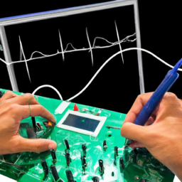
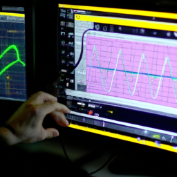
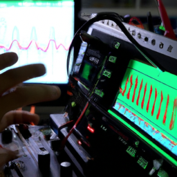
Now, let’s dive into the role of an oscilloscope when it comes to debugging your embedded systems. The importance of waveform analysis in troubleshooting embedded systems cannot be overstated.
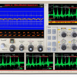
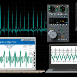
An oscilloscope allows you to visualize and analyze the electrical signals within your system, helping you identify any anomalies or issues. This is especially crucial when dealing with time-sensitive operations, as the oscilloscope can capture and display real-time waveforms.
The advantages of using an oscilloscope over other debugging tools are numerous. It provides a high level of accuracy and precision, allowing you to measure voltage, current, and frequency with great detail. Additionally, it offers a wide range of triggering options, enabling you to capture specific events or patterns of interest.
Overall, an oscilloscope is an invaluable tool for effectively diagnosing and resolving problems in your embedded systems.
Exploring the Capabilities of a Logic Analyzer for Efficient Debugging
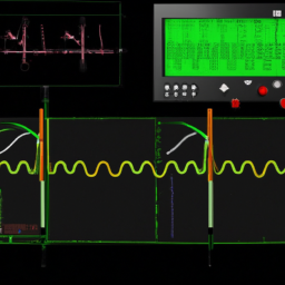
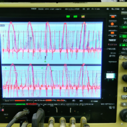
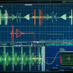
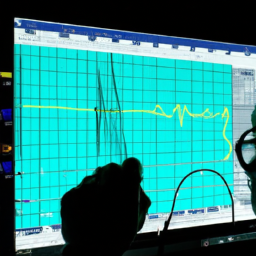
Additionally, a logic analyzer can capture and display waveforms in real-time, providing a vivid visual representation of the signals flowing through the embedded system. This capability is particularly useful when analyzing timing issues, as it allows you to accurately measure and compare the timing relationships between different signals.
By capturing and analyzing serial data, a logic analyzer can also help you understand the communication between different components in your system. It can decode various protocols such as I2C, SPI, UART, and CAN, giving you insight into the data being transmitted. This can be invaluable in identifying communication errors or protocol violations.
Furthermore, a logic analyzer often has a large memory depth, allowing you to capture long-duration events and analyze them in detail.
Overall, a logic analyzer complements an oscilloscope by providing a different set of tools for efficient debugging of embedded systems.
Choosing the Right Tool for Your Specific Debugging Needs
To choose the right tool for your specific debugging needs, consider the type of data you need to capture and analyze, as well as the level of detail and accuracy required.
When evaluating the cost effectiveness of oscilloscopes and logic analyzers for debugging, keep in mind that oscilloscopes are generally more expensive than logic analyzers. However, they offer the advantage of visualizing analog signals in addition to digital signals.
On the other hand, logic analyzers are specifically designed for digital signal analysis and can provide more detailed information about the digital signals.
Another factor to consider is the learning curve associated with using these tools. Oscilloscopes tend to have a steeper learning curve due to their wider range of functions and settings, while logic analyzers are typically easier to use for digital signal analysis.
Comparing the Display and Analysis Features of Oscilloscopes and Logic Analyzers
You can compare the display and analysis features of oscilloscopes and logic analyzers to see which tool is best suited for your specific debugging needs. While both tools have their own unique benefits, using them together can provide comprehensive debugging capabilities.
Oscilloscopes are ideal for visualizing and analyzing analog signals in real-time. They allow you to measure voltage levels, frequencies, and waveforms.
On the other hand, logic analyzers specialize in capturing and analyzing digital signals. They provide detailed timing and protocol analysis.
However, it is important to understand the limitations of both tools when dealing with complex embedded systems. Oscilloscopes may struggle with high-speed digital signals, while logic analyzers may not provide the level of detail needed for analyzing analog signals.
By using both tools together, you can overcome these limitations and achieve a more thorough debugging process.
Analyzing Analog Signals with an Oscilloscope
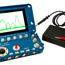
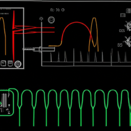
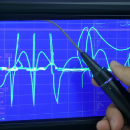
One fascinating aspect of using an oscilloscope is its ability to analyze analog signals in real-time, providing a captivating visual representation of voltage levels, frequencies, and waveforms.
Oscilloscopes are commonly used for troubleshooting electrical circuits, as they allow engineers to observe and measure various parameters of the signal. With an oscilloscope, you can easily identify anomalies such as noise, distortion, and voltage spikes, which are crucial for debugging embedded systems.
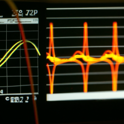
The advantage of using an oscilloscope for analyzing analog signals is that it provides a continuous waveform display, enabling you to observe the signal’s behavior over time. However, it’s important to note that while oscilloscopes excel at analyzing analog signals, logic analyzers are more suitable for capturing and analyzing digital data, making them advantageous in certain scenarios.
Interpreting Digital Signals with a Logic Analyzer
Now that you’ve learned about analyzing analog signals with an oscilloscope, let’s delve into the world of digital signals and how they can be interpreted using a logic analyzer.
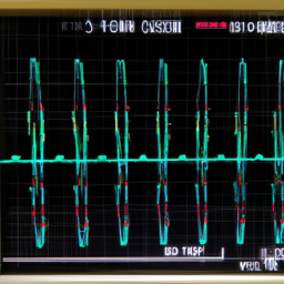
A logic analyzer is a powerful tool for debugging embedded systems that allows you to capture and analyze digital signals. It provides a detailed view of the logic levels and timing relationships between different signals. One key advantage of a logic analyzer over an oscilloscope is its ability to capture and display a large number of digital channels simultaneously.
Utilizing triggering capabilities for precise digital signal analysis is crucial when using a logic analyzer. By setting up triggers, you can capture specific events or conditions that are of interest for further analysis. This enables you to focus on the specific portions of the signal that are relevant to your debugging process.
In addition to triggering, understanding the importance of timing and synchronization in logic analyzer measurements is essential. Digital signals often rely on precise timing relationships, and a logic analyzer allows you to measure and analyze these relationships accurately. It ensures that you can identify any timing issues or synchronization problems that may be causing errors in your embedded system.
To emphasize the importance of timing and synchronization, let’s take a look at the following table:
| Signal A | Signal B | Signal C | Signal D |
|---|---|---|---|
| High | Low | High | High |
| Low | High | Low | High |
| High | High | Low | Low |
By analyzing the timing relationships between these signals, you can identify any patterns or irregularities that may be affecting the behavior of your embedded system.
A logic analyzer is an invaluable tool for interpreting digital signals in embedded systems. By utilizing its triggering capabilities and understanding the importance of timing and synchronization, you can effectively debug and troubleshoot your system to ensure its optimal performance.
Frequently Asked Questions
Can an oscilloscope be used to analyze digital signals?
Yes, an oscilloscope can be used to analyze digital signals, but it has its limitations. While it can display voltage waveforms over time, it may not provide detailed information about the digital signal’s logic states.
Logic analyzers, on the other hand, excel at capturing and analyzing digital signals. They offer advanced triggering capabilities, deep memory, and precise timing measurements. These advantages make logic analyzers a preferred tool for debugging embedded systems.
What are some common applications of logic analyzers in embedded system debugging?
In embedded system debugging, real-time data analysis is crucial for identifying and resolving issues efficiently. Logic analyzers play a vital role in this process by offering several benefits for protocol analysis. They provide a comprehensive view of digital signals, allowing you to capture and analyze high-speed, complex protocols.
With advanced triggering capabilities and deep memory, logic analyzers enable precise timing analysis and protocol decoding, enabling thorough debugging and optimization of embedded systems.
How does the sampling rate of an oscilloscope affect its ability to capture signals accurately?
Imagine you’re a detective trying to solve a crime. Your success depends on your ability to capture every piece of evidence accurately.
The same goes for an oscilloscope’s sampling rate. The higher the sampling rate, the more accurately it can capture signals. This directly affects the oscilloscope’s ability to accurately measure high frequency signals.
When comparing the performance of oscilloscopes and logic analyzers, the oscilloscope’s bandwidth plays a crucial role in ensuring signal accuracy.
Can a logic analyzer measure and analyze analog signals?
No, a logic analyzer cannot measure and analyze analog signals. Logic analyzers are specifically designed to capture and analyze digital signals. They operate on a binary level, detecting and interpreting high and low voltage levels. This is one of the limitations of logic analyzers compared to oscilloscopes.
Oscilloscopes, on the other hand, can measure and analyze both digital and analog signals, making them more versatile for debugging embedded systems.
What is the typical price range for both oscilloscopes and logic analyzers?
Typical price range for entry-level oscilloscopes and logic analyzers can vary depending on various factors.
Entry-level oscilloscopes generally range from $200 to $500, while logic analyzers typically range from $300 to $800.
Factors that affect the cost include bandwidth, sample rate, number of channels, and additional features like advanced triggering capabilities or built-in signal generators.
It’s important to consider your specific requirements and budget when selecting the right tool for your needs.
Conclusion
In conclusion, when it comes to debugging embedded systems, both oscilloscopes and logic analyzers play vital roles.
While an oscilloscope helps analyze analog signals, a logic analyzer is perfect for interpreting digital signals.
Choosing the right tool depends on your specific debugging needs.
Both devices offer unique display and analysis features, allowing you to identify and address issues efficiently.
Just like a skilled detective and a trusty magnifying glass, oscilloscopes and logic analyzers are like a dynamic duo in unraveling the mysteries of embedded system debugging.