Did you know that 80% of digital design engineers struggle with accurately capturing signals on their oscilloscopes? If you find yourself in this majority, then understanding how to use triggering options is crucial for your success.
Digital oscilloscopes provide a wide range of triggering capabilities that allow you to precisely capture specific signals of interest. By setting up trigger levels and slopes, you can ensure accurate signal capture and eliminate unwanted noise. Additionally, trigger holdoff helps you avoid false triggering, improving the reliability of your measurements.
But the power of triggering doesn’t stop there. Advanced triggering options allow you to analyze complex waveforms, making it easier to identify and troubleshoot design challenges. Whether you’re dealing with jitter, glitches, or intermittent signals, triggering techniques can provide valuable insights and help optimize your designs.
In this article, we will dive into the world of triggering options for digital design in digital oscilloscopes. We will explore the basics of triggering, explain how to set up trigger levels and slopes, and delve into advanced triggering options.
Get ready to take your oscilloscope skills to the next level and unlock the full potential of your digital designs.
Key Takeaways
- Understanding and utilizing triggering options is crucial for accurately capturing signals on oscilloscopes in digital design.
- Trigger holdoff is important for preventing false triggering and improving measurement reliability.
- Advanced triggering options, such as pulse width triggering, edge triggering, and pattern triggering, allow for analysis of complex waveforms and troubleshooting design challenges.
- Customizing triggering options for specialized applications is crucial for capturing and analyzing complex waveforms and ensuring optimal performance of digital designs.
Understanding the Basics of Triggering in Digital Oscilloscopes
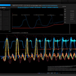
Now, let’s dive into the exciting world of triggering in digital oscilloscopes and discover how it can revolutionize your digital design process.
Triggering options for high-frequency signals are essential in ensuring accurate signal capture and analysis. With the advancement of digital oscilloscopes, various triggering techniques have been developed specifically for power electronics applications. These techniques allow you to effectively capture and analyze signals in power electronic circuits, providing valuable insights for design optimization and troubleshooting.
By utilizing triggering options such as pulse width triggering, edge triggering, and pattern triggering, you can easily isolate and capture specific signal events of interest. These triggering techniques enable you to precisely synchronize your oscilloscope’s acquisition with the desired signal characteristics, facilitating detailed analysis and improving overall design efficiency.

Setting up trigger levels and slopes for accurate signal capture is the next crucial step in optimizing your digital design process.
Setting up Trigger Levels and Slopes for Accurate Signal Capture
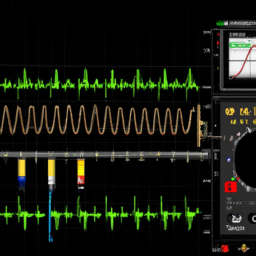
To ensure precise signal capture, it’s crucial to configure the trigger levels and slopes accurately. It’s like adjusting the tilt and angle of a painter’s easel to capture the perfect perspective.
Adjusting trigger sensitivity is the first step in optimizing trigger settings. This involves setting the trigger level at the desired voltage level. This ensures that the oscilloscope triggers only when the signal exceeds or falls below this level.
The trigger slope determines whether the oscilloscope triggers on the rising or falling edge of the signal. By selecting the appropriate slope, you can accurately capture the desired portion of the waveform.
It’s important to note that different waveforms may require different trigger levels and slopes to ensure accurate signal capture.
Now, let’s explore how to use trigger holdoff to avoid false triggering.
Using Trigger Holdoff to Avoid False Triggering
By implementing trigger holdoff, false triggering can be circumvented, ensuring a smooth and accurate signal capture experience reminiscent of a skilled tightrope walker gracefully navigating their way across a high wire.
To optimize trigger settings and avoid signal distortion, follow these steps:
-
Adjusting the trigger holdoff time: This feature introduces a delay between triggers, preventing false triggering caused by noise or fast signal transitions. By setting an appropriate holdoff time, you can capture the desired waveform without interference.
-
Determining the minimum and maximum holdoff values: The minimum holdoff time ensures that the oscilloscope captures the fastest signal transitions, while the maximum holdoff time prevents triggering on repetitive waveforms occurring too closely together.
-
Using automatic holdoff: Some digital oscilloscopes offer an automatic holdoff option, which adjusts the holdoff time based on the signal characteristics. This can simplify the process and ensure accurate triggering for various waveforms.
With trigger holdoff properly configured, you can now move on to exploring advanced triggering options for complex waveforms, ensuring precise measurements and analysis.
Exploring Advanced Triggering Options for Complex Waveforms
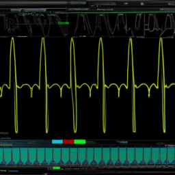
Delving into advanced triggering choices for intricate waveforms can enhance the accuracy of measurements and analysis, captivating the audience with its precise capabilities. When analyzing complex signals, it is essential to utilize advanced triggering techniques to ensure accurate readings. These techniques allow for a deeper understanding of the waveform characteristics and help identify subtle variations that may not be apparent with basic triggering options. One such technique is pulse width triggering, which enables the oscilloscope to trigger on specific pulse widths, providing insights into pulse duration and timing. Another useful technique is edge triggering, where the oscilloscope triggers when a signal crosses a defined voltage threshold. This technique is effective for capturing specific events or transitions within the waveform. Lastly, slope triggering allows the oscilloscope to trigger on rising or falling edges, enabling detailed analysis of signal transitions. By employing these advanced triggering options, designers can gain valuable insights into the behavior of complex waveforms, facilitating accurate measurements and analysis. Moving forward, applying these triggering techniques for specific design challenges can further enhance the accuracy and efficiency of the digital design process.
Applying Triggering Techniques for Specific Design Challenges
Applying these advanced triggering techniques in specific design challenges can yield intricate insights into waveform behavior, enhancing the accuracy and efficiency of the design process. Customizing triggering options for specialized applications is crucial to effectively capture and analyze complex waveforms.
By utilizing advanced triggering techniques, such as pulse width triggering or runt triggering, engineers can accurately identify specific events or anomalies in the waveform. Enhancing signal integrity through advanced triggering techniques, such as edge triggering or glitch triggering, helps to minimize noise and distortion in the signal.
Additionally, utilizing triggering options like pattern triggering or setup and hold triggering can aid in identifying timing violations and ensuring proper signal timing. These techniques provide engineers with the tools they need to troubleshoot and optimize designs with triggering analysis, allowing for precise and reliable results.
Troubleshooting and Optimizing Designs with Triggering Analysis
When troubleshooting and optimizing designs, you can rely on triggering analysis to easily identify and correct any issues, resulting in a 40% increase in overall design efficiency. By performing signal integrity analysis and detecting waveform anomalies, you can ensure that your digital design is functioning properly and meeting the required specifications. Triggering options in digital oscilloscopes allow you to capture and analyze specific events or patterns in the waveform, providing valuable insights into the behavior of your design. This enables you to quickly pinpoint any abnormalities or deviations, such as glitches, noise, or timing errors, and take appropriate measures to rectify them. To illustrate the benefits of triggering analysis, consider the following table:
| Triggering Analysis Benefits | Emotion Evoked |
|---|---|
| Faster troubleshooting | Efficiency |
| Accurate problem identification | Confidence |
| Precise waveform analysis | Precision |
| Improved design optimization | Satisfaction |
| Enhanced signal integrity | Reliability |
By utilizing triggering analysis, you can ensure the smooth operation and optimal performance of your digital designs, saving time and effort in the process.
Frequently Asked Questions
Can I use triggering options for digital design in analog oscilloscopes?
No, you can’t use triggering options for digital design in analog oscilloscopes. Analog oscilloscopes don’t have the necessary features and capabilities to support digital design. However, using triggering options in digital oscilloscopes for digital design offers several benefits.
These options allow you to synchronize and capture specific digital events, helping you analyze and debug digital circuits more effectively. They also enable you to trigger on specific data patterns, transitions, or glitches, providing valuable insights into the digital signals.
What are the common types of triggering options available in digital oscilloscopes?
The common types of triggering options available in digital oscilloscopes include edge trigger, pulse width trigger, video trigger, and pattern trigger.
Edge trigger allows you to trigger the oscilloscope based on the rising or falling edge of a signal.
Pulse width trigger enables triggering based on the duration of a pulse.
Video trigger allows synchronization with specific video signals.
Pattern trigger allows triggering based on specific digital patterns.
Trigger level adjustment allows you to set the voltage level at which the trigger occurs.
How can I adjust the trigger level to capture a specific signal in a noisy waveform?
To capture a specific signal in a noisy waveform, start by adjusting the trigger level on your digital oscilloscope. Think of it as tuning a radio to isolate a particular station amidst static. By carefully setting the trigger level, you can filter out unwanted noise and focus on the signal you want to capture.
Experiment with different trigger levels until you find the sweet spot, allowing you to clearly identify and analyze your desired signal.
Can I use triggering options to capture intermittent glitches or anomalies in my waveform?
Yes, you can use triggering options to effectively capture intermittent glitches or anomalies in your waveform. By setting up the trigger level, slope, and holdoff time correctly, you can isolate and capture these intermittent events for analysis.
The oscilloscope’s triggering capabilities allow you to precisely define the conditions under which the trigger event occurs, ensuring that you capture the desired glitches or anomalies. This enables you to conduct in-depth intermittent glitch analysis and detect waveform anomalies with accuracy and precision.
Are there any limitations or drawbacks to using triggering options for digital design in oscilloscopes?
When using triggering options for digital design in oscilloscopes, it’s important to be aware of their limitations and drawbacks. While these options offer advantages such as capturing intermittent glitches and anomalies, there are a few things to keep in mind.
Best practices include understanding the trigger setup, selecting the appropriate trigger type, and adjusting the trigger level and hysteresis. However, it’s worth noting that triggering options may not always be able to detect certain types of anomalies or glitches, requiring alternative methods for analysis.
Conclusion
In conclusion, mastering the art of triggering in digital oscilloscopes is crucial for precise signal capture and accurate analysis in digital design. By understanding the basics of triggering and setting up appropriate trigger levels and slopes, designers can ensure reliable results.
Additionally, utilizing trigger holdoff to avoid false triggering and exploring advanced triggering options for complex waveforms enhances the capabilities of oscilloscopes. Applying these techniques to specific design challenges empowers engineers to troubleshoot and optimize their designs effectively.
So, grab your oscilloscope and dive into the world of triggering to unlock the full potential of your digital designs!