Are you struggling with timing issues in your embedded systems? Frustrated with the inexplicable glitches and delays that hinder your project’s performance? Look no further!
In this article, we will explore the powerful tool that is the oscilloscope and how it can be your ultimate ally in debugging timing issues.
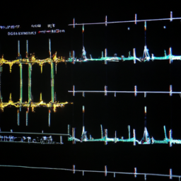
By combining the technical precision of an oscilloscope with your expertise, you can unlock a world of insights into your embedded systems. This dynamic duo will enable you to capture and analyze waveforms, identify timing issues, and employ advanced techniques to troubleshoot and debug with ease.
But that’s not all! We will also delve into best practices for preventing timing issues, ensuring that your future projects run like clockwork.
So strap in and get ready to unravel the mysteries of timing issues in embedded systems with the help of an oscilloscope. Let’s dive right in!
Key Takeaways
- Oscilloscope is a powerful tool for debugging timing issues in embedded systems
- Understanding oscilloscope features such as timebase, voltage scale, trigger settings, and probe attenuation is crucial
- Rise and fall times, pulse width, and duty cycle can help identify abnormalities causing timing issues
- Adjusting timebase and voltage scales helps in zooming in or out on specific portions of the waveform
Understanding the Basics of an Oscilloscope
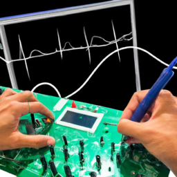
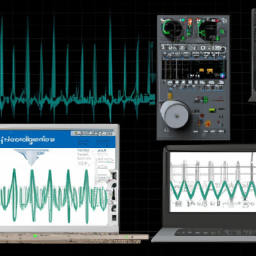
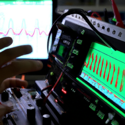
Now that you’ve got your hands on an oscilloscope, let’s dive into the basics and understand how this powerful tool can help you debug timing issues in your embedded systems.
Understanding oscilloscope features is crucial to effectively use it for debugging. Start by familiarizing yourself with the controls and settings such as timebase, voltage scale, trigger settings, and probe attenuation. This will allow you to accurately capture and analyze waveforms.
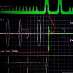
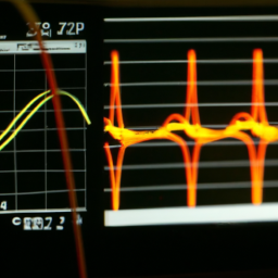
Interpreting waveform characteristics is another important aspect. Pay attention to the amplitude, frequency, and shape of the waveforms. This information can provide insights into the timing behavior of your embedded system. Additionally, observe the rise and fall times, pulse width, and duty cycle to identify any abnormalities that may be causing timing issues.
With a solid understanding of these basic concepts, you can leverage the oscilloscope’s capabilities to efficiently debug timing issues in your embedded systems.
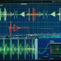
Capturing and Analyzing Waveforms
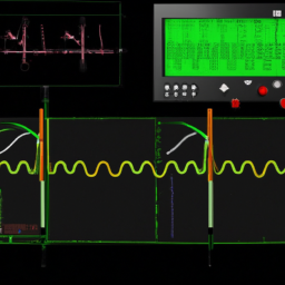
To capture and analyze waveforms effectively, you need to understand triggering and acquisition modes. These modes allow you to specify when and how data is captured, ensuring accurate and reliable measurements.
You also need to adjust the timebase and voltage scales. This enables you to zoom in or out on specific portions of the waveform, providing a clearer view of the signal.
Finally, you should utilize cursors and measurements. This allows you to quantify and analyze various aspects of the waveform, such as amplitude, frequency, and timing.
By following these steps, you can effectively capture and analyze waveforms.
Triggering and Acquisition Modes
Start by selecting the appropriate triggering and acquisition modes on your oscilloscope, allowing you to capture accurate data and pinpoint timing issues that may be causing frustrating delays or glitches in your embedded system.
Did you know that 80% of embedded system failures can be traced back to timing issues? To effectively capture waveforms, you can choose from various triggering modes such as edge triggering, pulse width triggering, or pattern triggering.
Edge triggering detects voltage changes at a specific threshold, while pulse width triggering captures waveforms based on the duration of pulses. Pattern triggering, on the other hand, allows you to capture waveforms based on specific digital patterns.
Additionally, you can utilize different acquisition techniques like single-shot acquisition, which captures a single waveform, or repetitive acquisition, which captures multiple waveforms in a continuous manner.
By carefully selecting the appropriate triggering and acquisition modes, you can ensure accurate and comprehensive waveform analysis to identify and resolve timing issues in your embedded system.
Adjusting Timebase and Voltage Scales
Fine-tune the timebase and voltage scales on your oscilloscope, allowing you to precisely analyze waveforms and gain a deeper understanding of the intricate workings of your circuitry.
Adjusting the timebase involves fine-tuning the measurements displayed on the oscilloscope’s screen. This optimization ensures that you capture and observe the desired portion of the waveform accurately. It allows you to zoom in or out of the waveform, making it easier to identify timing issues and anomalies.
Similarly, adjusting the voltage scales involves selecting the appropriate range to display the signal amplitudes correctly. By selecting the voltage scale that best matches the amplitude of the waveform, you can avoid signal distortion and accurately measure voltage levels. This step is crucial in understanding the behavior and characteristics of your circuitry, as it allows you to observe minute changes in voltage levels and identify any issues that may arise.
Adjusting the timebase and voltage scales on your oscilloscope is essential for fine-tuning measurements and optimizing the display. It enables you to gain a deeper understanding of your circuitry by accurately analyzing waveforms and interpreting signal amplitudes.
Using Cursors and Measurements
Now you can easily analyze waveforms and accurately measure voltage levels using cursors and measurements, enhancing your understanding and unleashing the full potential of your circuitry. Cursors in an oscilloscope allow you to precisely measure time intervals, voltage levels, and perform mathematical operations on waveforms. By placing cursors on specific points of interest, you can measure the time difference between two events, calculate frequency, and determine rise or fall times. Measurements provide essential information about the waveform, such as peak-to-peak voltage, average voltage, and RMS voltage. They also enable you to track changes in timing and voltage levels over time. To ensure accuracy and precision, always position the cursors on stable parts of the waveform and adjust them to encompass the desired portion. Troubleshooting tip: use measurements to compare different waveforms and identify anomalies.
| Measurement | Description | |
|---|---|---|
| Time Interval | Measure the time difference between two events | |
| Frequency | Calculate the frequency of a waveform | |
| Rise/Fall Time | Determine the time it takes for a waveform to transition between two voltage levels | |
| Peak-to-Peak Voltage | Measure the voltage difference between the highest and lowest points of a waveform | |
| RMS Voltage | Calculate the root mean square voltage of a waveform | … which represents the effective voltage of the waveform and is used to determine its power or heating effect on a load. |
Identifying Timing Issues
To identify timing issues in your embedded system, you need to be able to recognize common problems that can occur.
This includes understanding how to analyze signal integrity issues, such as noise and interference, that can affect the timing of your signals.
Additionally, you should be able to detect jitter and glitches, which can cause timing inaccuracies and errors in your system.
By being able to identify these timing issues, you can effectively debug and optimize the timing of your embedded system.
Recognizing Common Timing Problems
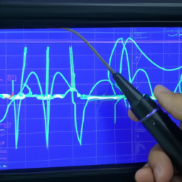
Don’t be a clueless detective, it’s time to put on your oscilloscope glasses and spot those sneaky timing problems lurking in your embedded systems. When it comes to identifying latency issues, an oscilloscope is your trusty companion.
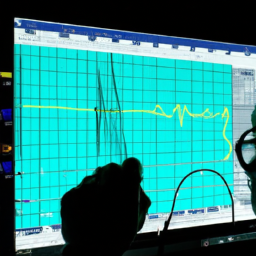
It allows you to visualize the timing of signals and identify any delays or inconsistencies. By carefully analyzing the waveform patterns, you can pinpoint the source of the problem and take appropriate action.
Additionally, an oscilloscope is invaluable in troubleshooting synchronization problems. It helps you analyze the timing relationship between different signals and identify any discrepancies. Whether it’s a delay in signal propagation or a synchronization issue between multiple components, the oscilloscope provides the necessary insights to resolve these problems effectively.
So grab your oscilloscope and start uncovering those elusive timing issues in your embedded systems.
Analyzing Signal Integrity Issues
Signal integrity problems can seriously impact the performance and reliability of your design, so it’s essential to analyze and address them effectively.
When using an oscilloscope to debug timing issues in embedded systems, it’s important to also analyze signal integrity issues. These issues can occur due to signal reflection and impedance mismatch.
To effectively analyze signal integrity issues, consider the following:
-
Signal Reflection:
- Understand the causes and effects of signal reflection.
- Use the oscilloscope’s high bandwidth and fast sampling rate to capture and analyze reflected signals.
- Use time-domain reflectometry (TDR) to locate and measure the magnitude of reflection points.
-
Impedance Mismatch:
- Identify impedance mismatches in your system.
- Use the oscilloscope to measure and analyze the voltage and current waveforms at different points in the system.
- Use the oscilloscope’s advanced triggering capabilities to capture intermittent impedance mismatch events.
By following these steps, you can effectively analyze signal integrity issues and ensure the optimal performance and reliability of your embedded system design.
Detecting Jitter and Glitches
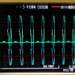
Jitter and glitches can disrupt the smooth flow of signals, causing erratic fluctuations and disturbances in the visual representation of data. When using an oscilloscope to debug timing issues in embedded systems, it’s crucial to be able to detect and analyze these signal noise problems.
Jitter refers to the variation in the timing of a signal, while glitches are sudden, short-lived disturbances. To detect jitter and glitches, you can use the oscilloscope’s time-domain view to observe the waveform and identify any unexpected variations. This view allows you to analyze frequency fluctuations and measure the timing parameters accurately.
By carefully examining the signal’s waveform and comparing it to the expected behavior, you can pinpoint the source of the timing issue and take appropriate corrective actions to ensure proper functioning of the embedded system.
Using Advanced Oscilloscope Techniques
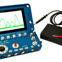
Explore the vast capabilities of your oscilloscope to unlock a treasure trove of insights and overcome timing issues like a skilled detective unraveling a complex mystery.
By utilizing advanced oscilloscope settings and conducting advanced waveform analysis, you can delve into the intricate details of your embedded system’s timing behavior.
Advanced oscilloscope settings allow you to fine-tune the parameters to capture and analyze waveforms with greater precision. Adjusting the timebase, voltage scale, and trigger settings can help you isolate specific timing issues and identify their root causes.
In addition, advanced waveform analysis techniques provide a deeper understanding of the timing characteristics of your system. Features like eye diagrams, jitter analysis, and pulse width measurements enable you to detect subtle timing variations, glitches, and irregularities that may be causing your timing issues.
By leveraging these advanced oscilloscope techniques, you can confidently navigate the complexities of debugging timing issues in embedded systems, leading to more efficient and reliable designs.
Troubleshooting and Debugging Strategies
When troubleshooting and debugging timing issues in embedded systems, it’s crucial to be able to isolate and localize the problem. This involves identifying the specific area or component that’s causing the timing issue.
Using trigger holdoff and delay can be an effective strategy to capture and analyze the precise timing events that are causing the problem.
Additionally, employing proper probing techniques is essential for obtaining accurate measurements and ensuring that the signals being analyzed aren’t distorted or affected by the measurement setup.
Isolating and Localizing Timing Issues
To effectively diagnose timing issues in embedded systems, it’s essential to pinpoint and confine the problem areas, ensuring a thorough understanding of the root cause.
Here are three key steps to isolating and localizing timing issues:
-
Review the system design: Start by examining the timing requirements and constraints specified in the system design. This will help you identify potential areas where timing issues may arise.
-
Analyze the code: Dive into the code and look for any sections that involve time-sensitive operations, such as interrupts, timers, or delays. Check for any potential race conditions, synchronization problems, or incorrect time calculations.
-
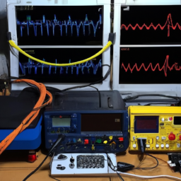
Utilize an oscilloscope: Connect an oscilloscope to relevant signals or pins to measure and visualize the timing behavior. Use triggering and time measurement features to capture and analyze the timing relationships between different system components.
By following these steps, you can effectively isolate and localize timing issues, allowing for efficient troubleshooting and resolution of timing problems in embedded systems.
Using Trigger Holdoff and Delay
By implementing trigger holdoff and delay, you can enhance your understanding of the intricate timing relationships within your system, allowing for more precise analysis and troubleshooting. Adjusting trigger settings is crucial in isolating and localizing timing issues. The trigger holdoff feature ensures that the oscilloscope ignores any subsequent triggers for a specified amount of time after the initial trigger event. This prevents false triggers caused by overlapping signals or noise. On the other hand, the trigger delay feature allows you to delay the triggering of the oscilloscope’s acquisition, giving you the ability to capture signals that occur before the trigger event.
To further illustrate the importance of trigger holdoff and delay, consider the following scenario:
| Trigger Holdoff | Trigger Delay |
|---|---|
| 5 ns | 2 μs |
| 10 ns | 4 μs |
| 20 ns | 8 μs |
| 50 ns | 20 μs |
In this table, different combinations of trigger holdoff and delay settings are shown. By adjusting these parameters, you can better understand the signal propagation and timing relationships within your embedded system. This knowledge enables you to pinpoint and resolve timing issues more effectively.
Probing Techniques for Accurate Measurements
Proper probing practices provide precise measurements for optimal analysis and troubleshooting. When it comes to probing techniques for accurate measurements and signal integrity analysis, there are several key considerations to keep in mind.
-
Use a high-quality and properly calibrated probe to ensure accurate measurements.
-
Minimize the length of the probe leads to reduce signal degradation.
-
Place the probe tip as close as possible to the measurement point to minimize signal loading.
-
Use proper grounding techniques to avoid ground loops and ensure accurate measurements.
By following these probing techniques, you can obtain accurate and reliable measurements for your oscilloscope analysis.
This will help you identify timing issues and troubleshoot your embedded systems effectively. Remember, precise measurements are crucial for understanding and resolving timing problems in your designs.
Best Practices for Preventing Timing Issues
One of the most essential steps in preventing timing issues is ensuring proper synchronization between different components of the embedded system. This synchronization is crucial for preventing timing errors and optimizing system performance.
To achieve this, it’s important to follow several best practices. Firstly, use clock signals with low jitter and precise frequency to ensure accurate timing measurements.
Secondly, minimize the length and impedance of signal traces to reduce signal reflection and ensure fast signal propagation.
Additionally, avoid using long and complex interrupt service routines that may cause delays in critical timing operations.
Furthermore, implement proper buffering techniques to prevent contention and reduce signal degradation.
Lastly, utilize advanced debugging tools like an oscilloscope to monitor and analyze the timing behavior of the system, enabling detection and resolution of any potential timing issues.
By following these best practices, you can effectively prevent timing issues and optimize the performance of your embedded system.
Frequently Asked Questions
Can I use an oscilloscope to measure the frequency of a signal?
If you’re wondering whether you can use an oscilloscope to measure the frequency of a signal, the answer is a resounding yes! Oscilloscopes are incredibly useful tools for measuring frequency accuracy and characterizing signals.
By connecting the signal to the oscilloscope’s input, you can observe the waveform and use the timebase settings to determine the frequency. With its precise measurements and detailed display, an oscilloscope is an essential instrument for any engineer dealing with signal analysis.
How do I choose the appropriate oscilloscope probe for my application?
To choose the appropriate oscilloscope probe for your application, you need to consider common challenges in selecting probes for high frequency applications. The characteristics of the probe have a significant impact on the signal integrity and measurement accuracy. Factors such as bandwidth, attenuation ratio, input impedance, and probe loading should be carefully evaluated.
It’s crucial to choose a probe that can accurately capture and maintain the integrity of the high frequency signals you’re working with.
Can an oscilloscope help me identify and debug intermittent timing issues?
If you’re struggling with intermittent timing issues, fear not! An oscilloscope can come to your rescue. With its powerful debugging techniques, you can easily identify and resolve these pesky problems.
By analyzing signal waveforms, you’ll be able to pinpoint the exact moment when timing goes awry. This precise and detailed approach will ensure you can tackle any timing issue head-on and get your embedded systems running smoothly.
Is it possible to use an oscilloscope to measure the rise and fall times of a digital signal?
To measure the rise and fall times of a digital signal, you can use an oscilloscope. By using an oscilloscope for signal integrity analysis, you can accurately measure the timing characteristics of the signal.
This includes measuring the rise time, which is the time it takes for the signal to transition from a low to a high level, and the fall time, which is the time it takes for the signal to transition from a high to a low level.
Additionally, an oscilloscope can also measure signal jitter and skew, providing further insight into the timing behavior of the signal.
Are there any specific settings or configurations on an oscilloscope that can help me detect and analyze timing issues more effectively?
To effectively detect and analyze timing issues using an oscilloscope, there are specific settings and configurations you can utilize.
Firstly, the oscilloscope triggering capabilities are crucial. By setting the trigger level and slope appropriately, you can capture the desired events accurately.
Additionally, adjusting the oscilloscope timebase settings, such as the time per division and horizontal position, allows you to zoom in on the specific timing details of interest.
These settings enable a precise and detailed analysis of timing issues in embedded systems.
Conclusion
In conclusion, mastering the art of using an oscilloscope to debug timing issues in embedded systems is crucial for any technical expert. By understanding the basics of this powerful tool, capturing and analyzing waveforms, and using advanced techniques, you can effectively identify and troubleshoot timing problems.
Implementing best practices to prevent such issues in the future is also essential. So, delve into the world of oscilloscopes, and with persistence and precision, unravel the mysteries of timing in embedded systems.