Are you a beginner in the world of electronics? Do you find yourself baffled by terms like oscilloscope and multimeter? Fear not! In this beginner’s guide, we will demystify these essential tools and equip you with the knowledge to use them effectively.
Imagine this scenario: You are working on a project and suddenly, you encounter a circuit malfunction. You have no idea where to begin troubleshooting. Enter the oscilloscope and multimeter – your trusty companions in the world of electronic diagnostics.
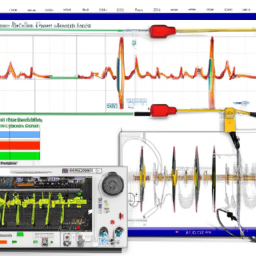
An oscilloscope is like a window into the inner workings of a circuit, allowing you to visualize electrical waveforms. On the other hand, a multimeter measures various electrical quantities, such as voltage and resistance.
In this guide, you will learn the fundamentals of an oscilloscope and multimeter, from understanding their basic functions to troubleshooting circuits and analyzing waveforms. We will also share some tips and tricks to enhance your oscilloscope and multimeter usage.

So, let’s dive in and embark on this exciting journey into the realm of electronic diagnostics!
Key Takeaways
- The oscilloscope is a tool that provides a window into the inner workings of a circuit, allowing for the analysis of waveforms and signal integrity.
- The multimeter is a device used to measure voltage, current, and resistance in a circuit, and it is essential to select the appropriate range and zero out the meter for accurate readings.
- Troubleshooting circuits requires patience and attention to detail, as common issues such as loose connections, faulty components, short circuits, and noise interference can affect the performance of the circuit.
- To effectively use an oscilloscope and multimeter, it is crucial to calibrate the devices, use the correct probes and leads, and avoid common mistakes that could impact the accuracy of measurements.
Understanding the Basics of an Oscilloscope
Now that you’ve familiarized yourself with the multimeter, let’s dive into the world of oscilloscopes and understand how they work.
Oscilloscopes are powerful tools that allow you to visualize and analyze electronic signals. To effectively use an oscilloscope, it’s essential to understand its controls and how to interpret the measurements it provides.
The main controls of an oscilloscope include the timebase control, the vertical control, and the trigger control. The timebase control determines the horizontal scale of the display, while the vertical control adjusts the amplitude of the signal. The trigger control ensures that the oscilloscope captures the waveform correctly.

Interpreting the measurements on an oscilloscope involves understanding the voltage and time scales, as well as identifying important features such as frequency, amplitude, and wave shape. By mastering these skills, you can effectively use an oscilloscope to analyze and troubleshoot electronic circuits.
Mastering the Functions of a Multimeter
Explore the multitude of functions your trusty multimeter has to offer, as it effortlessly measures voltage, current, and resistance with just a simple turn of the dial. To ensure accuracy, follow these tips:
- Select the appropriate range: Adjust the dial to the highest range initially and then gradually decrease it until you get a precise reading.
- Zero out the meter: Before taking a measurement, make sure to zero out the meter by connecting the test leads together and adjusting the zero adjustment knob.
- Avoid common mistakes: Be mindful of common multimeter mistakes, such as using the wrong test lead, forgetting to set the meter to the correct function, or not allowing enough time for the reading to stabilize.
By mastering these functions and avoiding common mistakes, you can maximize the accuracy and usefulness of your multimeter. Remember to always consult the user manual for specific instructions and safety precautions.
Troubleshooting Circuits with an Oscilloscope
When troubleshooting circuits with an oscilloscope, you need to analyze waveforms and signal integrity. By carefully examining the waveforms, you can identify any abnormalities or anomalies that may be causing circuit issues.

Once these issues are identified, you can then proceed to fix them by implementing appropriate measures.
Analyzing Waveforms and Signal Integrity
By observing the dance of the waves on the oscilloscope screen, you can unravel the secrets of signal integrity with the precision of a master conductor. Waveform analysis techniques are essential in understanding the quality of a signal and diagnosing any issues in a circuit.
When analyzing a waveform, start by examining the amplitude, which represents the strength of the signal. A distorted or weak amplitude can indicate problems such as noise interference or signal attenuation.
Next, focus on the frequency, which determines how quickly the signal oscillates. An incorrect frequency can lead to timing errors and data corruption.
Additionally, analyze the shape of the waveform, looking for abnormalities like overshoot, undershoot, or ringing. These anomalies can be signs of impedance mismatches or improper termination.
By interpreting signal integrity through waveform analysis, you can identify and rectify circuit issues effectively.
Identifying and Fixing Common Circuit Issues
Unraveling the secrets of signal integrity is like solving a puzzle, where identifying and fixing common circuit issues becomes an exhilarating challenge.
When troubleshooting circuit problems, it’s essential to have a systematic approach. Start by checking for loose connections or faulty components, as these are often the culprits behind circuit malfunctions. Use your multimeter to measure voltage, current, and resistance at various points in the circuit to pinpoint the problem area.
Look out for short circuits, open circuits, or incorrect component values. Another common issue is noise interference, which can be caused by inadequate grounding or nearby electromagnetic interference. By using your oscilloscope, you can analyze the waveform and identify any abnormalities that may be affecting the circuit’s performance.
Remember, patience and attention to detail are key when it comes to troubleshooting circuit problems.
Measuring Voltage with a Multimeter
To accurately measure voltage with a multimeter, you must first set the meter to the appropriate voltage range and then connect the probes to the circuit. This allows you to obtain precise readings and ensure the safety of the measurement process. When using a multimeter, it is important to understand the different voltage ranges available and select the one that is closest to the expected voltage. This helps to avoid overloading the meter and damaging the circuit. Once the range is set, you can connect the black probe to the ground or negative terminal and the red probe to the positive terminal of the circuit. The multimeter will then display the voltage reading on its screen. Remember to take note of the polarity and units of the voltage measurement.
| Function | Symbol | Description |
|---|---|---|
| Voltage | V | Measures the electrical potential difference between two points in a circuit. |
| Resistance | Ω | Measures the opposition to the flow of electric current in a circuit. |
| Continuity | ∞ | Tests the presence of a complete path for electric current flow in a circuit. |
| Current | A | Measures the flow of electric charge in a circuit. |
Analyzing Waveforms with an Oscilloscope
The oscilloscope helps us analyze waveforms for a better understanding of electrical signals. Here are four essential waveform analysis techniques to help you interpret oscilloscope readings:
-
Timebase: Adjust the timebase setting to control the horizontal scale of the waveform display. This allows you to measure the time period and frequency of the signal accurately.
-
Voltage Measurement: Use the vertical controls to measure the voltage amplitude and identify any fluctuations or irregularities in the waveform.
-
Triggering: Set the trigger level to stabilize the waveform display by synchronizing it with a specific part of the signal. This helps you capture repetitive waveforms consistently.
-
Waveform Shape: Analyze the shape of the waveform, such as its symmetry, rise time, and fall time, to determine the characteristics of the electrical signal.
By mastering these waveform analysis techniques and interpreting oscilloscope readings, you can gain valuable insights into the behavior of electrical signals and troubleshoot circuit issues effectively.
Tips and Tricks for Effective Oscilloscope and Multimeter Use
Now that you’ve learned how to analyze waveforms with an oscilloscope, let’s dive into some tips and tricks for effectively using both an oscilloscope and a multimeter. Achieving accurate measurements is crucial, so it’s important to pay attention to a few key considerations.
First, always ensure that your oscilloscope and multimeter are properly calibrated and set up for the specific measurement you’re performing. Secondly, make sure to use the correct probes and leads for the task at hand, as using the wrong ones can lead to inaccurate readings.
Additionally, it’s important to avoid common mistakes such as using improper ground connections or overlooking signal integrity issues. By following these tips and avoiding these mistakes, you’ll be well on your way to obtaining precise and reliable measurements.
Frequently Asked Questions
What are some common safety precautions to keep in mind when using an oscilloscope and multimeter?
When using an oscilloscope and multimeter, it’s essential to prioritize electrical safety and proper grounding. To ensure your safety, always wear appropriate personal protective equipment, such as insulated gloves and safety goggles.
Before starting any measurements, verify that the equipment is properly grounded and follow the manufacturer’s instructions for safe operation. Remember to never touch live circuits with your bare hands and avoid working on equipment in wet or damp environments.
Can an oscilloscope and multimeter be used interchangeably for all measurements?
No, an oscilloscope and multimeter cannot be used interchangeably for all measurements. Although both devices are used for measuring electrical quantities, they have different limitations and accuracies.
An oscilloscope is primarily used for visualizing and analyzing waveforms, while a multimeter is used for measuring voltage, current, and resistance.
While a multimeter provides accurate measurements for DC and low-frequency AC signals, an oscilloscope is more accurate for measuring high-frequency signals and can capture transient events with greater detail.
How can I choose the appropriate probes for my oscilloscope and multimeter?
To choose the appropriate probes for your oscilloscope and multimeter, start by considering their purpose. Probe selection is like finding the perfect tool for a job. Determine the voltage range, frequency, and signal type you’ll be working with.
High voltage probes are ideal for measuring high voltages, while current probes are used for measuring current. Take into account the probe’s bandwidth and attenuation ratio.
Make an informed choice to ensure accurate and reliable measurements.
Are there any specific considerations when using an oscilloscope or multimeter with high-frequency signals?
When working with high-frequency signals, there are specific considerations to keep in mind. High-frequency signal analysis requires specialized techniques to accurately measure and analyze these signals.
To ensure accurate measurements, it’s important to reduce noise in oscilloscope measurements. This can be achieved by using proper grounding techniques, shielding, and employing differential probing.
Additionally, it’s essential to adjust the oscilloscope settings, such as the bandwidth, sampling rate, and input impedance, to match the frequency of the signal being measured.
Are there any limitations to the accuracy of measurements taken with an oscilloscope and multimeter?
When using an oscilloscope, it’s important to be aware of its limitations. Oscilloscope measurements may have limitations due to factors such as bandwidth, sample rate, and input impedance. These limitations can affect the accuracy of the measurements taken, particularly when dealing with high-frequency signals.
On the other hand, multimeter measurements are generally accurate, but their accuracy can be affected by factors such as the quality of the instrument and the precision of the components being measured.
Conclusion
In conclusion, you’ve now gained a solid foundation in using an oscilloscope and multimeter. By understanding the basics, mastering the functions, and troubleshooting circuits, you’re well-equipped to tackle any electrical project.
Remember, "practice makes perfect," so don’t hesitate to experiment and refine your skills. With these tools in your arsenal, you can confidently measure voltage, analyze waveforms, and ensure the efficiency of your circuits.
So dive in, explore, and let your curiosity guide you on your journey to becoming an expert in oscilloscope and multimeter use.