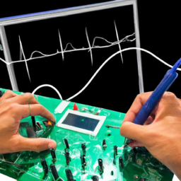
Are you tired of spending hours trying to find those elusive analog signal issues in your embedded systems? Frustrated with the endless trial and error approach? Well, fret no more! We have the ultimate solution that will make your troubleshooting endeavors a breeze. Enter the mighty oscilloscope! With its unparalleled power and precision, this tool is your key to unlocking the secrets of analog problems in your embedded systems.
In this article, we will guide you through the ins and outs of using an oscilloscope to debug analog issues. From setting up your oscilloscope for optimum performance to identifying and analyzing signal problems, we will leave no stone unturned.
We will dive into the world of triggering and measurements, helping you pinpoint those pesky issues with ease. And to top it all off, we will share some valuable troubleshooting techniques and best practices to save you time and effort.
So, get ready to take your analog troubleshooting skills to the next level with the help of an oscilloscope. Let’s dive in and conquer those stubborn analog issues once and for all!
Key Takeaways
- Proper calibration of oscilloscope settings is crucial for accurate measurements.
- Waveform characteristics such as voltage levels, frequency, amplitude, and timing should be analyzed to identify analog issues.
- Triggering and measurements help in pinpointing and addressing analog signal problems.
- Troubleshooting techniques and best practices, such as checking power supply and connections, analyzing waveforms, and studying case studies, are important for resolving analog issues.
Understanding the Basics of an Oscilloscope
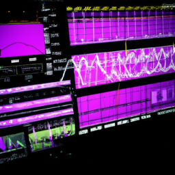
Understanding the basics of an oscilloscope is crucial in order to effectively debug analog issues in embedded systems. Oscilloscope features such as bandwidth, sample rate, and input impedance play a vital role in accurately capturing and analyzing signals.
When troubleshooting analog issues, it’s important to select the appropriate voltage range and time base settings on the oscilloscope to ensure optimal signal visualization. Additionally, using the trigger function allows you to stabilize and capture repetitive waveforms.
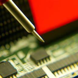
To accurately measure voltage levels and timing parameters, it’s essential to properly calibrate the oscilloscope probes. Grounding and shielding techniques should also be employed to minimize noise interference.
Understanding these oscilloscope features and troubleshooting tips will enable you to efficiently identify and resolve analog issues in embedded systems.
Setting up Your Oscilloscope for Analog Troubleshooting
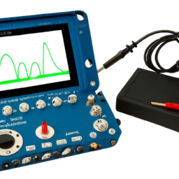
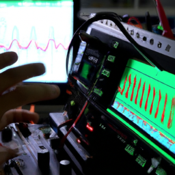
To get started with troubleshooting analog problems, you’ll want to ensure your oscilloscope is properly equipped, like a well-prepared detective with all the necessary tools at hand. One of the first steps is calibrating the oscilloscope settings to ensure accurate measurements. This involves adjusting the vertical and horizontal scales, as well as the trigger level, to match the signal you are analyzing. By doing so, you can obtain a clear and precise waveform representation on the oscilloscope screen.
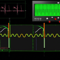
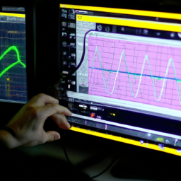
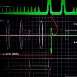
Once your oscilloscope is calibrated, it’s time to interpret the waveform characteristics. This involves analyzing the voltage levels, frequency, amplitude, and timing of the waveform. Look for any abnormalities, such as noise, distortion, or unexpected fluctuations. By understanding the waveform characteristics, you can identify and diagnose any analog issues in your embedded system.
To help you grasp the importance of calibrating oscilloscope settings and interpreting waveform characteristics, let’s take a look at the following table:
| Waveform Characteristic | Importance |
|---|---|
| Voltage levels | Crucial |
| Frequency | Key indicator |
| Amplitude | Essential |
| Timing | Vital |
By paying attention to these factors, you’ll be better equipped to troubleshoot analog problems using your oscilloscope effectively.
Identifying and Analyzing Analog Signal Problems
Once your oscilloscope is properly calibrated, you can dive into the fascinating world of identifying and analyzing analog signal problems. To help you navigate this world, here are some common analog signal issues you may encounter:
-
Voltage level problems: This occurs when the voltage doesn’t reach the expected level, which can indicate issues with the power supply or signal integrity.
-
Noise and interference: These can manifest as random fluctuations or unwanted signals that disrupt the intended waveform.
-
Distortion: This refers to any alteration of the waveform shape, such as changes in amplitude or frequency.
-
Signal anomalies: This includes glitches, spikes, or dropouts that can occur intermittently or consistently.
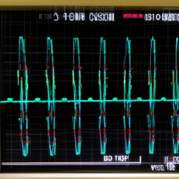
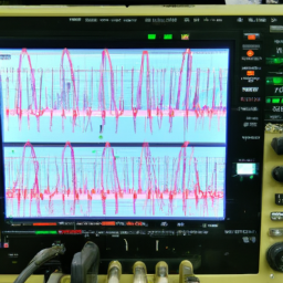
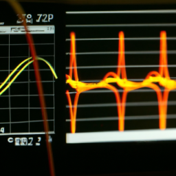
To interpret oscilloscope waveforms effectively, pay attention to the amplitude, frequency, and timing of the signal. Look for abnormalities and compare them to expected values. Use cursors and measurements to accurately quantify the signal characteristics. By mastering these skills, you’ll be well-equipped to tackle analog signal issues in your embedded systems.
Using Triggering and Measurements to Pinpoint Issues
By mastering the techniques of triggering and measurements, you can effectively pinpoint and address any problems that may arise in your embedded system’s analog signal. When it comes to troubleshooting common analog issues in embedded systems, these advanced techniques are crucial.
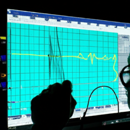
Triggering allows you to capture specific events or conditions that trigger the oscilloscope to start acquiring data, enabling you to focus on the problem area. By setting up appropriate triggers, you can capture intermittent issues or specific signal patterns, making it easier to identify the root cause.
Additionally, measurements provide essential quantitative data about the signal, such as voltage levels, frequencies, and timings. With accurate measurements, you can compare the expected values with the actual ones, helping you identify deviations and potential issues.
By utilizing triggering and measurements, you can effectively debug analog issues and ensure optimal performance in your embedded system.
Troubleshooting Techniques and Best Practices
Mastering troubleshooting techniques and best practices is essential for identifying and resolving any problems that may arise in your system, ensuring optimal performance and reliability.
When it comes to troubleshooting analog issues in embedded systems using an oscilloscope, there are some common problems that you may encounter. These can include noise, distortion, signal integrity issues, and improper grounding.
Troubleshooting these issues requires a systematic approach. Start by checking the power supply and connections, ensuring they’re stable and properly grounded. Then, analyze the waveforms using triggering and measurements to pinpoint the source of the problem.
Additionally, studying troubleshooting case studies can provide valuable insights and techniques for resolving complex issues.
By following these best practices, you can effectively diagnose and address common analog issues in your embedded systems.
Frequently Asked Questions
Can I use an oscilloscope to debug digital signal issues in embedded systems?
Yes, an oscilloscope can be used to diagnose and troubleshoot digital signal corruption in embedded systems. To effectively troubleshoot digital signal issues, follow these best practices with an oscilloscope:
-
Set the oscilloscope to the appropriate voltage and time scales.
-
Use triggering to stabilize the waveform.
-
Analyze the signal integrity, including rise/fall times and noise levels.
-
Use advanced features like eye diagrams and serial protocol analysis for deeper analysis.
An oscilloscope is a valuable tool for debugging digital signal issues in embedded systems.
How do I choose the appropriate voltage range and time scale on my oscilloscope?
To choose the appropriate voltage range on your oscilloscope, start by determining the maximum voltage level you expect to measure. Set the voltage range to a level that’s slightly higher than this maximum value. This will ensure that the waveform is displayed accurately without any distortion.
To set the time scale, consider the frequency of the signal you’re analyzing. Choose a time scale that allows you to clearly see multiple cycles of the waveform on the screen. Adjust the time scale as needed to zoom in or out on specific sections of the signal.
What are some common sources of noise in analog signals and how can I eliminate them?
To eliminate common sources of noise in analog signals, there are several techniques you can employ.
First, make sure you understand the impact of impedance mismatch on your signals. This involves matching the impedance of your signal source, transmission lines, and load to minimize reflections and signal degradation.
Additionally, using shielding techniques, such as twisted pair cables or ferrite beads, can help reduce electromagnetic interference.
Grounding techniques, like star grounding, can also be effective in minimizing noise.
Can an oscilloscope help me identify the root cause of intermittent analog signal problems?
Yes, an oscilloscope can be a valuable tool in identifying the root cause of intermittent analog signal problems. By using the oscilloscope troubleshooting techniques, you can capture and analyze the waveform of the signal. This allows you to observe any irregularities or abnormalities that may be causing the intermittent issues.
With the precise measurements and detailed analysis provided by the oscilloscope, you can effectively troubleshoot and pinpoint the source of the problem.
Are there any limitations or drawbacks to using an oscilloscope for analog troubleshooting?
When it comes to using an oscilloscope for analog troubleshooting, there are a few limitations and drawbacks to be aware of.
One limitation is the accuracy of the measurements. Although oscilloscopes provide precise visual representations of signals, the accuracy of the measurements can be affected by factors such as noise and signal distortion.
Additionally, the limited bandwidth of the oscilloscope can restrict the analysis of high-frequency signals.
It’s important to consider these limitations to ensure accurate and effective troubleshooting.
Conclusion
In conclusion, mastering the use of an oscilloscope is essential for effectively debugging analog issues in embedded systems. By understanding the basics of this powerful tool and setting it up correctly, you can accurately identify and analyze signal problems.
Utilizing triggering and measurements allows you to pinpoint the root cause of issues with precision. Remember to employ troubleshooting techniques and adhere to best practices for efficient problem-solving.
With the oscilloscope as your trusted ally, you’ll navigate the intricate landscape of analog troubleshooting like a skilled cartographer mapping uncharted territories.