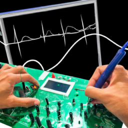
Are you tired of spending hours trying to debug your embedded systems, only to end up more frustrated than when you started? Well, fear not, because we have the solution for you! In this article, we will delve into the world of oscilloscopes and explore the common mistakes that people make when using them to debug embedded systems.
Now, we know what you’re thinking. How can using an oscilloscope be so difficult?’ Well, my dear reader, let us enlighten you. Despite its seemingly straightforward nature, using an oscilloscope to debug embedded systems requires a certain level of finesse and know-how. One wrong move, and you could find yourself down a rabbit hole of confusion and wasted time.
But fear not, for we are here to guide you through the intricate world of oscilloscope debugging. We will break down the most common mistakes people make, from improperly setting up the oscilloscope to using the wrong probes and connections. We will also tackle more advanced topics, such as troubleshooting power supply issues and testing communication protocols.
So, grab your oscilloscope and get ready to debug like a pro. With our expert tips, you’ll be able to avoid these common mistakes and effortlessly debug your embedded systems.
Let’s dive in!
Key Takeaways
- Proper setup and calibration of the oscilloscope are crucial for accurate measurements and waveform interpretation.
- Using the correct probes and connections, along with proper positioning, minimizes signal distortion and interference.
- Understanding waveform characteristics and optimizing oscilloscope settings help troubleshoot issues and capture desired data.
- Analyzing power supply issues, communication protocols, signal integrity, and timing helps identify and resolve problems in embedded systems.
Understanding the Oscilloscope’s Features and Functions
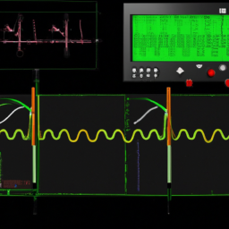
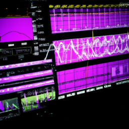
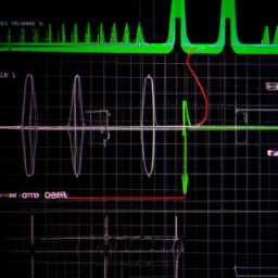
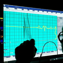
Don’t overlook the power of the oscilloscope’s features and functions – they can be your secret weapons in unraveling the mysteries of embedded systems! When debugging with an oscilloscope, it’s crucial to interpret waveform measurements accurately.
This means understanding how to read and analyze the different waveforms displayed on the screen, such as voltage, frequency, and timing. Additionally, optimizing the oscilloscope settings for specific debugging tasks is essential.
This includes adjusting the timebase, voltage scale, and triggering options to capture and analyze the signals of interest effectively. By mastering these features and functions, you can confidently navigate through the complexities of embedded systems and identify and resolve issues more efficiently.
So, make sure to familiarize yourself with your oscilloscope’s capabilities and utilize them to their full potential.
Properly Setting Up the Oscilloscope
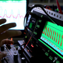
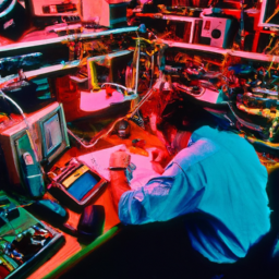
Ensure you’ve properly configured the oscilloscope to capture accurate and detailed data, leaving no room for uncertainty. Start by calibrating the oscilloscope to ensure accurate measurements.
Check the calibration frequency and adjust it if necessary. Use a reliable calibration source to verify the accuracy of the oscilloscope’s measurements.
Next, select the appropriate timebase for your measurements. This determines the duration of time displayed on the screen. Choose a timebase that allows you to capture the relevant waveform details without losing resolution. Keep in mind that a faster timebase may provide more detailed information, but it may also introduce noise or aliasing. Conversely, a slower timebase may result in a loss of waveform details.
Therefore, it’s crucial to strike a balance between capturing detailed information and avoiding artifacts.
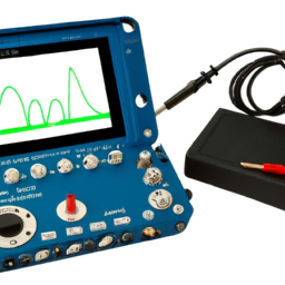
Using the Correct Probes and Connections
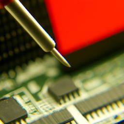
Using the appropriate probes and making the correct connections is crucial for obtaining accurate and reliable data when working with an oscilloscope. Proper probe positioning is vital to ensure that the signal being measured is not distorted or affected by any external factors.
It is important to place the probe tip as close as possible to the signal source to minimize any signal degradation. Additionally, maintaining proper signal integrity is essential. This can be achieved by using high-quality probes with low capacitance and impedance to minimize any interference or loading effects.
Furthermore, ensuring that the probe ground lead is properly connected to the ground reference point is important to prevent any ground loops or noise pickup. By following these guidelines, you can ensure that you obtain precise and reliable measurements when debugging embedded systems with an oscilloscope.
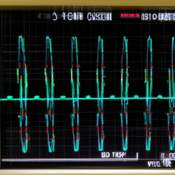
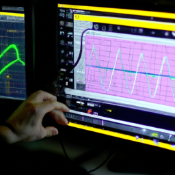
Capturing and Analyzing Data Effectively
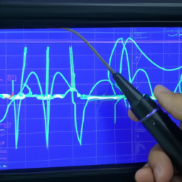
To truly harness the power of an oscilloscope, it’s like diving into a pool of data where every ripple and wave holds the key to unlocking the mysteries of your circuit. Interpreting waveform characteristics is crucial for effective data analysis. By understanding the different waveform shapes, such as square waves, sine waves, and pulses, you can identify abnormalities and troubleshoot issues. Optimizing oscilloscope settings is also essential. Adjusting the timebase, vertical scale, and triggering options allows you to capture the desired data and eliminate noise. Additionally, using advanced features like mask testing and math functions can provide further insights into the behavior of your circuit. Remember to carefully analyze the captured data, noting any anomalies or unexpected patterns, to efficiently debug your embedded system.
| Waveform Characteristic | Interpretation |
|---|---|
| Amplitude | Measure the peak-to-peak voltage or voltage difference between two points on the waveform. |
| Frequency | Determine the number of cycles occurring in a given time period. |
| Rise/Fall Time | Measure the time it takes for a waveform to transition from one voltage level to another. |
Troubleshooting Power Supply Issues
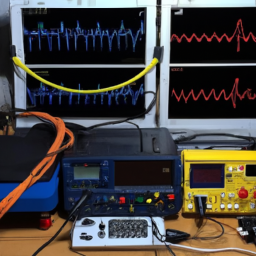
When troubleshooting power supply issues, you can visualize the flow of electricity through your circuit like a river. This allows you to trace the path of current and identify any blockages or disruptions.
To troubleshoot grounding problems, connect the oscilloscope’s ground clip to a known good ground point in your circuit. This ensures accurate measurements and helps avoid ground loop issues.
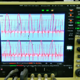
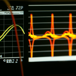
Additionally, use the oscilloscope to identify voltage spikes that may be causing power supply problems. Set up the oscilloscope to capture voltage waveforms and look for sudden, unexpected increases in voltage. These spikes can be caused by faulty components or noise in the power supply.
By capturing and analyzing these voltage spikes, you can pinpoint the source of the power supply issue and take appropriate corrective measures.
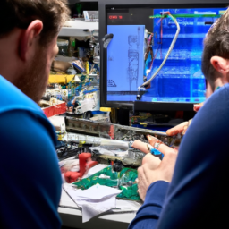
Testing and Debugging Communication Protocols
Oh, the joy of testing and debugging communication protocols! When it comes to embedded systems, ensuring the proper functioning of communication protocols is crucial. To do this, you need to analyze signal integrity and identify any timing issues that may arise. Signal integrity refers to the quality and reliability of the signals being transmitted between devices. It is important to check for any noise, distortion, or signal degradation that could affect the communication. Additionally, timing issues can occur when signals are not synchronized properly, leading to data corruption or loss. To resolve timing issues, you may need to adjust clock settings, improve synchronization methods, or implement buffering techniques. By diligently analyzing signal integrity and resolving timing issues, you can ensure the smooth and reliable operation of communication protocols in your embedded system.
| Signal Integrity Issues | Timing Issues | Resolution |
|---|---|---|
| Noise | Synchronization Issues | Adjust clock settings |
| Distortion | Data corruption | Improve synchronization methods |
| Signal degradation | Data loss | Implement buffering techniques |
Frequently Asked Questions
Can I use any oscilloscope for debugging embedded systems, or are there specific models that are better suited for this purpose?
When it comes to debugging embedded systems, it’s advisable to use specific oscilloscope models that are better suited for this purpose. Not all oscilloscopes are created equal, and some models offer distinct advantages.
The best oscilloscope models for debugging embedded systems provide higher bandwidth and sampling rates, allowing for accurate capture of fast signals. They also offer advanced triggering options and deep memory depth, enabling thorough analysis and troubleshooting of complex systems.
Are there any recommended techniques for minimizing noise and interference when setting up the oscilloscope?
To minimize noise and interference when setting up your oscilloscope, employ these techniques:
-
First, ensure proper calibration of the instrument to guarantee accurate measurements.
-
Second, use shielded cables to reduce electromagnetic interference.
-
Third, position the oscilloscope and its probes away from sources of electromagnetic radiation.
-
Fourth, employ proper grounding techniques to minimize ground loops.
-
Finally, consider using differential probes to eliminate common-mode noise.
By implementing these techniques, you can improve the reliability and accuracy of your oscilloscope measurements.
How can I ensure that I am using the correct probes and connections for my specific embedded system?
To ensure accurate measurements with proper probe selection, start by understanding the requirements of your specific embedded system. Consider factors such as signal frequency, voltage levels, and connector types.
Choosing the right probes and connections is crucial to prevent signal degradation or incorrect readings. Select probes with appropriate bandwidth and attenuation settings, ensuring they match your system’s specifications.
Use proper connectors and cables that minimize interference and maintain signal integrity.
What are some common challenges that one might encounter when capturing and analyzing data with an oscilloscope, and how can they be overcome?
When capturing and analyzing data with an oscilloscope, you may face common challenges in data analysis. To overcome these challenges, here are some tips for effective oscilloscope debugging.
First, ensure your oscilloscope settings are correctly configured for accurate measurements.
Second, use appropriate triggering to capture the desired waveform.
Third, pay attention to probe attenuation and impedance matching to avoid signal distortions.
Lastly, perform thorough signal analysis using measurements, math functions, and advanced triggering capabilities to gain deeper insights into your system’s behavior.
Are there any specific power supply issues that are commonly overlooked when troubleshooting embedded systems, and how can they be identified and resolved?
To effectively identify and resolve power supply issues in embedded systems, it’s crucial to set up your oscilloscope with precision. Begin by minimizing noise and interference using techniques like proper grounding and shielding.
Ensure accurate voltage measurements by selecting appropriate probe attenuation and compensating for probe loading. Use the scope’s triggering capabilities to capture power supply glitches and transients.
By meticulously configuring your oscilloscope, you can pinpoint and rectify power supply problems in your embedded systems.
Conclusion
In conclusion, mastering the art of debugging embedded systems with an oscilloscope is no easy task. It requires a deep understanding of the oscilloscope’s features and functions, as well as the proper setup and use of probes and connections.
Effective data capture and analysis techniques are essential for successful troubleshooting. Additionally, being able to tackle power supply issues and testing communication protocols is crucial.
Just like an oscilloscope meticulously examines and dissects electronic signals, you too must meticulously examine and dissect the problems at hand to uncover their true essence and find the optimal solution.
Only by doing so can you truly harness the power of the oscilloscope and conquer the challenges that come with debugging embedded systems.