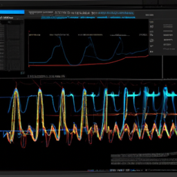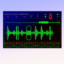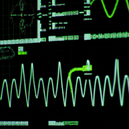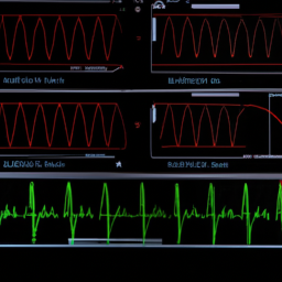
In the realm of digital oscilloscope applications, triggering options serve as powerful tools that unlock the true potential of these devices. Like a skilled conductor directing a symphony, these triggers orchestrate the measurement process, capturing and revealing elusive signals that would otherwise be lost in the noise.
In this article, we will explore five real-world examples of triggering options that can be employed to troubleshoot communication protocols, debug power electronics, analyze RF signals, identify transient events, and capture digital signals. By harnessing the capabilities of these triggers, you can delve into the intricate details of your waveform, uncovering hidden insights and ensuring the integrity of your signals.
So, fasten your seatbelt and embark on a journey through the fascinating world of digital oscilloscope applications, where triggers play a vital role in unraveling the mysteries of signals.
Key Takeaways
- Triggers in digital oscilloscope applications unlock the true potential of the devices and allow for the capture and reveal of elusive signals.
- Troubleshooting communication protocols involves using triggering options to capture and analyze data packets, identify timing errors, noise interference, and incorrect data transmission.
- Analyzing RF signals involves spectrum analysis, understanding frequency components, and identifying transient events to gain insights into the behavior of wireless systems.
- Investigating signal integrity issues includes resolving ground loop problems and mitigating the effects of electromagnetic interference (EMI) using digital oscilloscopes with triggering options.
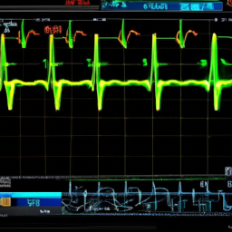
Troubleshooting Communication Protocols
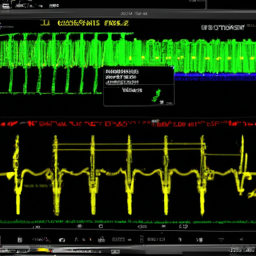
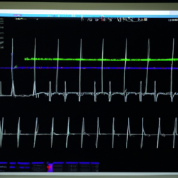
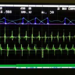
To troubleshoot communication protocols, you can use triggering options on the digital oscilloscope to capture and analyze the data packets in real-time. This is especially useful when troubleshooting serial connections and analyzing CAN bus issues.
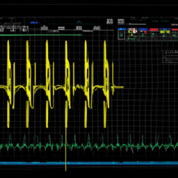
The triggering options allow you to set specific conditions that must be met for the oscilloscope to capture a waveform. For example, you can set a trigger condition based on a specific data pattern or a specific voltage level. By capturing the data packets that meet these trigger conditions, you can analyze the waveform to identify any issues with the communication protocol. This can help you pinpoint problems such as timing errors, noise interference, or incorrect data transmission.
Once you have resolved any communication protocol issues, you can move on to the subsequent section about debugging power electronics.
Debugging Power Electronics
When debugging power electronics, you can visualize the waveforms and pinpoint anomalies using the various settings and features available on your oscilloscope. Here are some ways you can utilize your oscilloscope to effectively debug power electronics:
-
Evaluating voltage fluctuations: By examining the voltage waveforms, you can identify any fluctuations or irregularities that may be causing issues in your power electronics circuitry.
-
Resolving circuit board faults: With the help of your oscilloscope, you can analyze the waveforms to detect and diagnose faults in the circuit board, such as short circuits or open circuits.
-
Utilizing triggering options: The oscilloscope’s triggering options allow you to capture specific events or abnormalities in the power electronics signals, which can aid in troubleshooting and identifying the root cause of any issues.
-
Adjusting timebase and voltage scales: By adjusting these settings, you can zoom in or out on the waveforms to get a clearer view of the power electronics signals and detect any anomalies.
-
Using math functions: The oscilloscope’s math functions enable you to perform mathematical operations on the waveforms, helping you analyze and interpret the power electronics signals more effectively.

Now, let’s move on to analyzing RF signals in the next section.
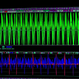
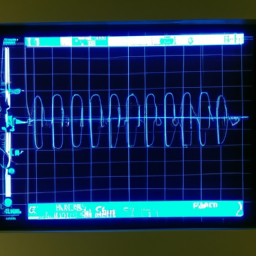
Analyzing RF Signals
Analyzing RF signals can be an exciting and captivating process as it delves into the truth behind theories, evoking emotional responses in the audience.
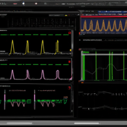
Spectrum analysis is a fundamental technique used in this process, allowing engineers to understand the frequency components present in an RF signal. By examining the spectrum, one can identify the different frequencies and their amplitudes, aiding in the characterization and troubleshooting of RF systems.
Another important aspect of analyzing RF signals is frequency modulation, which involves varying the frequency of a carrier signal according to the information being transmitted. This modulation technique is widely used in various communication systems.
Understanding and analyzing RF signals provides valuable insights into the behavior of wireless systems.
Transitioning into the subsequent section about identifying transient events, it becomes evident that analyzing RF signals is just one piece of the puzzle in comprehending the intricacies of digital oscilloscope applications.
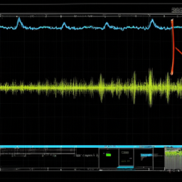
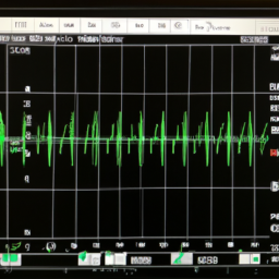
Identifying Transient Events
Identifying transient events is crucial in gaining a comprehensive understanding of the complexities of RF signal analysis and the behavior of wireless systems.
In order to accurately analyze RF signals, it’s important to detect voltage spikes and analyze signal distortion. Transient events, such as sudden changes in voltage or disturbances in the waveform, can provide valuable insights into the performance and integrity of the signal.
By detecting voltage spikes, you can identify potential issues or anomalies that may affect the overall performance of the RF system. Additionally, analyzing signal distortion can help uncover any changes or distortions in the waveform that may indicate signal degradation or interference. These insights are essential for troubleshooting and optimizing RF systems.
Moving forward, capturing digital signals will allow for further analysis and evaluation of the signal’s characteristics and performance.
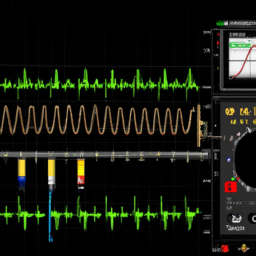
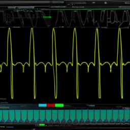
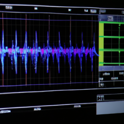
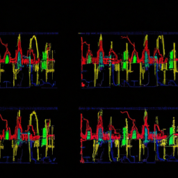
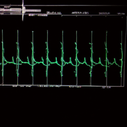
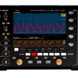
Capturing Digital Signals
To capture digital signals effectively, you need to ensure that your measurement equipment is capable of accurately capturing and analyzing the complex waveforms present in wireless systems. This involves measuring signal bandwidth, which refers to the range of frequencies that can be accurately captured by the oscilloscope.
By selecting an oscilloscope with a high bandwidth, you can capture digital signals with minimal distortion and accurately analyze the data transmission. Additionally, it’s important to consider the sample rate of the oscilloscope, which determines how frequently the waveform is sampled. A higher sample rate allows for a more detailed representation of the digital signal.
By carefully considering these factors and selecting the appropriate oscilloscope, you can effectively capture and analyze digital signals in wireless systems. This will enable you to investigate signal integrity issues and ensure optimal performance.
Investigating Signal Integrity Issues
Explore the depths of signal integrity issues by delving into the intricate world of wireless systems. In order to ensure reliable and accurate data transmission, it is crucial to identify and resolve ground loop problems and investigate electromagnetic interference (EMI) issues. Ground loops occur when there are multiple paths for current flow, causing unwanted noise and distortions in the signal. By using a digital oscilloscope with triggering options, you can effectively isolate and diagnose ground loop problems. Additionally, EMI issues can arise from external sources such as power lines or nearby electronic devices. With the advanced capabilities of a digital oscilloscope, you can analyze and mitigate the effects of EMI, ensuring the integrity of your signals. Take advantage of the triggering options in real-world digital oscilloscope applications to effectively investigate and resolve signal integrity issues.
| Signal Integrity Issues | Digital Oscilloscope Benefits |
|---|---|
| Ground Loop Problems | Isolate and diagnose issues |
| EMI Issues | Analyze and mitigate effects |
Frequently Asked Questions
How can I troubleshoot communication protocols using a digital oscilloscope?
To troubleshoot communication protocols using a digital oscilloscope, you can analyze signal integrity and investigate potential issues.
Start by connecting the oscilloscope to the communication lines and capturing the signals. Use triggering to isolate specific events or data packets for closer examination.
Ensure that the signals are clean and free from noise or distortions. Analyze the timing, voltage levels, and waveform characteristics to identify any abnormalities or errors in the communication protocol.
What are some common challenges in debugging power electronics with a digital oscilloscope?
In power electronics debugging, waveform analysis is crucial. It allows you to identify and troubleshoot common issues, such as voltage spikes, noise, and power supply problems. By using a digital oscilloscope, you can accurately measure and analyze waveforms to pinpoint the source of the problem.
Some common challenges include high-frequency switching noise, voltage regulation issues, and transient response problems. Solutions involve adjusting probe settings, using appropriate triggering options, and employing filtering techniques to improve signal quality.
How can a digital oscilloscope help in analyzing RF signals?
When analyzing RF signals, a digital oscilloscope can help ensure signal integrity. It does this by capturing and displaying the waveform accurately. One key advantage of using a digital oscilloscope for RF signal analysis is real-time spectrum analysis. This allows you to analyze the frequency spectrum in real-time, providing crucial insights into signal characteristics and potential interference. By combining precise waveform capture with spectrum analysis, a digital oscilloscope empowers you to make informed decisions and optimize RF system performance.
What are some techniques for identifying transient events using a digital oscilloscope?
To identify transient events using a digital oscilloscope, you can employ various techniques. Comparing different trigger options for digital oscilloscopes is crucial in this process.
Some common techniques include setting a voltage or time threshold for triggering, using edge triggering to capture specific transitions, and employing pulse width triggering to capture pulses of a specific duration. These techniques help in accurately capturing and analyzing transient events, allowing for precise measurements and troubleshooting.
How does a digital oscilloscope capture and analyze digital signals?
To capture and analyze digital signals, a digital oscilloscope utilizes various signal processing techniques. The sample rate and bandwidth are crucial factors in accurately capturing digital signals. A higher sample rate allows for the capture of fast-changing signals, while a wider bandwidth ensures that the oscilloscope can accurately reproduce high-frequency components of the signal.
These parameters are essential for obtaining precise measurements and detailed analysis of digital signals.
Conclusion
In conclusion, digital oscilloscopes offer a wide range of triggering options that are invaluable in various real-world applications. Whether you’re troubleshooting communication protocols, debugging power electronics, analyzing RF signals, identifying transient events, capturing digital signals, or investigating signal integrity issues, these oscilloscopes provide precise and informative data for your analysis.
Just like a skilled detective, these oscilloscopes act as your Sherlock Holmes, unraveling the mysteries of electrical signals and unveiling the hidden truths. So, equip yourself with a digital oscilloscope and become the master of signal investigation.